CNC Benders
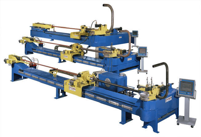
Fig. 1 Jesse Co. CNC Pipe Benders. 20' load length is standard.
BENDERS FOR TODAY
1000CNC series benders are CNC controlled 3-axis benders - hydraulically powered on all axes. With the proper bending tools, they have the power, accuracy, and rigidity to produce wrinkle free bends, with a minimum of ovality and wall thinning, in pipe and tubing of various metals and alloys.
Jesse Co. benders are engineered and built to state of the art machine tool standards, including JIC. Their capacities are stated in terms of Sch. 80 pipe - not a thin-wall tube whose section modules may only be half as great. Standard capacities are: 3", 4", 6", 8" IPS (60.3, 88.9, 114.3, 168.2, 219mm) - and larger.
AN IMPROVED DESIGN
Benders are more rugged, and versatile than traditional "swing arm" benders. Because no swing arm or pressure die mechanism hangs below the plane of the bend die, the main frame of a 1000CNC series bender is positioned where it ought to be, directly beneath and supporting the pressure die slide. Thus, all the bending forces - exerted by the spindle and resisted by the pressure die - are directly "resolved" within a single, compact heavy duty, tubular beam. Jesse Co. 1000CNC series benders also have the largest spindle and bearing diameters, the greatest spread between bearings, and the smallest distance from bend die to upper spindle bearing - all to insure the greatest possible rigidity.
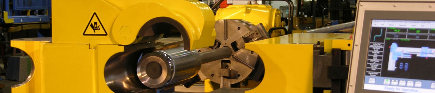
INTEGRAL ("OVERHEAD") CLAMP
By mounting the hydraulic clamping mechanism on the rotating bend die itself, Jesse Co. has eliminated the conventional swing-arm. There are many advantages to this system.
Built-in clamp alignment in the matching mounting surfaces of the clamp mechanism and bend die assure that no vertical or horizontal clamp set-up adjustment is required. Therefore tool changing is faster and easier.
The clamp opens upwards, eliminating interference with the forward feed of the bent workpiece. Potential interference between the clamp and the advancing workpiece is a major shortcoming of traditional swing arm benders. This problem is usually overcome by the use of a cam or linage type drop-down clamping mechanism or by a separately pivoted coaxial swing arm and main shaft. Both are complex, compromise "fixes". Jesse Co.'s overhead clamp system eliminates this problem.
Clamping forces are self contained - not carried through the die mount, the spindle, or any other part of the machine. Thus, there is never any bend-die tilt caused by clamping forces.
No overhead tie bar is required with an overhead clamp, because there is no clamp-pressure induced bend die tilt - even when bending the heaviest or most "critical" workpieces.
Tooling remains properly aligned because the bend die rotates in a level plane throughout the bend.
Machine and tooling maintenance are reduced. There are no swing arm slides or toggle linkages to sear or break, and less stress and wear on the tooling.
Overhead clamping is safer. The dangerous "pinch point" between the swing arm and pressure die arm is gone.
The operator has direct control of the clamping forces. They are easily read on a pressure gauge and easily set with a relief valve, assuring consistent, accurate set-ups. (Toggle type clamp mechanisms generate unreadable, and necessarily excessive, forces at their top-dead-center, pre-lock up position.)
PRESSURE DIE SYSTEM
The pressure die mounts on a massive master-bar carrier riding on oversized ways which are attached directly to the main beam - not to a cantilevered arm.
The direct acting pressure die cylinder is mounted in the centerline plane of the tube to directly resist the bending forces.
The pressure die carrier slide and the masterbar are long enough to permit making 3xD 90º bends at the machine's rated capacity. (Greater lengths are available).
All set up pressure adjustments are made from the control console
Pressure die/carriage collision protection software prevents damaging collisions which can otherwise occur through operator error - i.e. due to closing the pressure die when the carriage has been advanced into the pressure die area.
PRESSURE DIE ASSIST (OR BOOSTER) FOR REDUCED WALL THINNING Unlike other benders, the pressure die assist and booster systems on Jesse Co. 1000-PC series benders are not "add-ons". The pressure die assist/booster cylinder is integrated into the pressure die carrier head - parallel to the centerline of the workpiece, where it ought to be, so that it won't impose any asymmetrical loads. The massive pressure die carrier ways on Jesse Co. 1000 series benders can accommodate the loads imposed by a booster system. Both the lateral pressure die assist/boost pressure are adjustable from the CNC control.
Pressure die assist bending involves the use of controlled push-force applied to the pressure die. This reduces tool drag and helps control workpiece thinning. However, since the pressure die is not clamped to the workpiece, total assist force is limited by the co-efficient of friction between the pressure die and the tube. Pressure die assist bending is not the same as boost bending.
Booster bending (optional) involves a continuous push-force applied directly to the workpiece through a booster clamp. To achieve maximum booster effect, the booster cylinder and its mounting system must be able to exert a sufficient load to bring the workpiece close to compressive yield. With the Jesse Co. boost system, the booster clamp is mounted directly on the rear of the pressure die, which then provides continuous column strength reinforcement of the workpiece under high booster loads. A sequence of up to ten pre-selected boost pressures are automatically applied as designated degree-of-bend points are reached.
"Shaped groove" no-mandrel bending (optional) combines special tools with pressure die assist (or optional boost for shorter radius bends) permitting non-mandrel bending of a broad range of pipe and heavier walled tube while minimizing wall thinning and ovality.
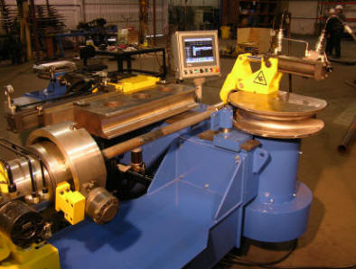 Fig. 2 Jesse Co. 1004 CNC Pipe Bender
The "Overhead" clamp opens upwards; eliminating the interference with the forward feed of the bent workpiece; a common problem with traditional swing arm benders.
CARRIAGE/MANDREL SYSTEM
The carriage/mandrel beam incorporates the mandrel extractor cylinder and mandrel rod supports together with the ways for the carriage.
The basic bender is complemented by the carriage/mandrel beam unit, without design compromises to either. Because the main beam and drive cylinders are under the pressure die slide, rather than under the mandrel beam, as in most benders, the carriage is designed to accommodate the centerline height of the bender's tooling, not vice versa. When a carriage is added to a traditional swing arm bender, the centerline height of the bend die must be elevated to accommodate the carriage collet's height above the main beam. This extra tooling height compounds the risk of bend die tilt.
Jesse Co.'s 1000 series design eliminates that problem. The standard 20' (6.1m) carriage travel and load length is also not restricted by the bender's main beam length and does not require an extended frame or other modifications.
The carriage rides on precision ground, round ways for smooth travel (distance-between-bend movement) - driven by a powerful hydraulic motor through a rack and pinion. During the bending cycle, this drive is declutched to allow free towing of the carriage as the tube is drawn around the radius die. Carriage boost is also available.
Chuck rotation (plane-of-bend movement) is also hydraulically driven, through an extremely low-backlash worm gear. For greater accuracy, the plane of bend rotation encoder is directly driven from the worm gear drive shaft, without any secondary drive mechanism.
Two collet/chuck options are available, a jaw type chuck for heavy walled or pre-flanged tube or a collet mechanism for thinner walled tube. the carriage and chuck/collet have sufficient power and grip to sustain all movements on both axes within the machine's capacity.
Mandrel rod/workpiece supports within the beam automatically retract as the carriage passes overhead.
20' (6.1m) over-mandrel load length and carriage travel assure being able to load full pipe lengths in one continuous motion with no hitch feeding. Greater load lengths are available.
Mandrel tangent position set up adjustment is accomplished by a lead screw on the mandrel extractor cylinder - an improvement over the traditional method of screwing the mandrel in and out on the end of the mandrel rod.
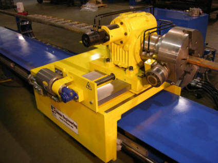 Fig. 3 Power centerline radius adjustment of the carriage and the mandrel unit during set-up is standard on 1000 CNC series benders.
POPULAR CNC SYSTEM
Jesse Co. has been offering CNC Pipe Benders since the early 1980's. In 1999 Jesse partnered with Current Tech to implement BendPro, a sophisticated CNC control.
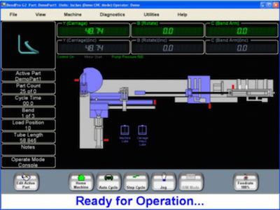
Today, BendPro G2 is the most popular CNC bender control in the industry. Customers tell us that it offers the highest performance and functionality of any CNC bender control on the market, and is the easiest to use.
- Backed by the best support in the industry
- BendPro G2 software (New Generation)
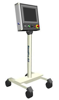
- Industrial PC with touch screen and bright, easy to read 15" LCD
- Windows XP Professional operating system with remote diagnostics
- Networks with office PCs, measuring machines, and the internet
- Off the shelf components are readily available worldwide
- Unlimited part storage via resident disk drives or office network
- High performance servo control assures fast and accurate production
- High speed I/O system links to PC via Ethernet
- XYZ or YBC (LRA) data entry and conversions supported
- Imports programs from office computers
- Displays and rotates 3D image of programmed part in real time
- Easy to use control screens with graphical representation of bender
- Open and closed Collet modes supported
- Hitch moves and recapture in zones supported
- Advanced diagnostics make troubleshooting problems a snap
- Interfaces to measuring machines made by Multi Systems, Romer, Axila, Addison, and others...
- Interfaces to robotic loaders and unloaders (Including CNC Bender Cells)
- Office software available for 'offline' programming and pre-bending checks
- Office software available for simulation, checks for part/machine interference
- Teach Mode for easy programming of complex interference moves
- And much more...
Standard Features:
BendPro G2 CNC
Separate Hydraulic Power unit
Overhead Clamp
Rack and Pinion automatic lubrication
Drive Chain automatic lubrication
Mandrel lubrication
Powered Cross Slides
Pressure Die Assist
Standard Scope of Supply:
Main Frame
Pipe Positioning Carriage & Frame
Mandrel Extractor & Rod
Hydraulic Power Unit
BendPro G2 CNC control
Overhead Clamp
Start-up kit
Factory Training
Operation & Maintenance manuals
| Specifications | 1003CNC | 1004CNC | 1006CNC | 1008CNC | 1010 CNC |
| Maximum Pipe Size | 3/80 | 4/80 | 6/80 | 8/80 | 10/80 |
| Maximum OD | 4.0" | 5.0" | 8.0" | 10.0" | 12.0" |
| Minimum OD (suggested) | 0.84" | 1.030" | 1.900" | 3.500" | 4.500" |
| Wall Thickness @ Max OD | .1875" | .1875" | .250" | .250" | .250" |
| Maximum CLR | 15" | 12" | 18" | 24" | 30" |
| Maximum Spindle Rotation | ≥193º | ≥193º | ≥193º | ≥193º | ≥193º |
| Maximum Length over mandrel | 20' | 20' | 20' | 20' | 20' |
| Working Height | 42" | 42" | 42" | 52" | 60" |
| Tooling Centerline Height | 2.500" | 3.000" | 4.375" | 6.000" | 7.000" |
| Mandrel Stroke | 22" | 24" | 28" | 30" | 36" |
| Follower Stroke | 19.5" | 25" | 33" | 44" | 55" |
| Pressure Die Stroke | 12" | 13" | 30" | 35" | 43" |
| Hydraulic Tank Capacity | 40 gal. | 80 gal. | 120 gal. | 180 gal. | 180 gal. |
| Hydraulic System Pressure | 3000 psi | 3000 psi | 3000 psi | 3000 psi | 3000 psi |
| Length Rearwards | 29' | 29' | 30' | 31'-4" | 32' |
| Length Forwards | 10" | 15" | 18" | 23" | 24" |
| Mandrel Rod OD | 1.66" | 1.90" | 2" | 2.31" | 3" |
| Mandrel Thread | 1.25"-12 | 1.75"-10 | 2"-12 | 2"-12 | 3"-12 |
| Standard Clamp | # 2 | # 3 | # 4 | # 5 | # 6 |
| Overall Width | 78" | 112" | 11' | 17'-4" | 18'-8" |
| Height | 54" | 56" | 60" | 78" | 84" |
| Weight (lbs) | 11,000 | 16,000 | 24,000 | 28,000 | 32,000 |
| Speeds | |||||
| C-Axis Fwd/Rev (rpm) | 1.3 / 3.2 | 1.0 / 3.4 | .60 / 3.7 | .60 / 2.2 | .60 / 2.2 |
| B-Axis (rpm) | 3 | 3 | 2 | 1.5 | 1.5 |
| Y-Axis (fpm) | 60 | 60 | 40 | 40 | 40 |
Specifications, capacities, and design features described are subject to change without notice.