Power Carriage Benders
.jpg)
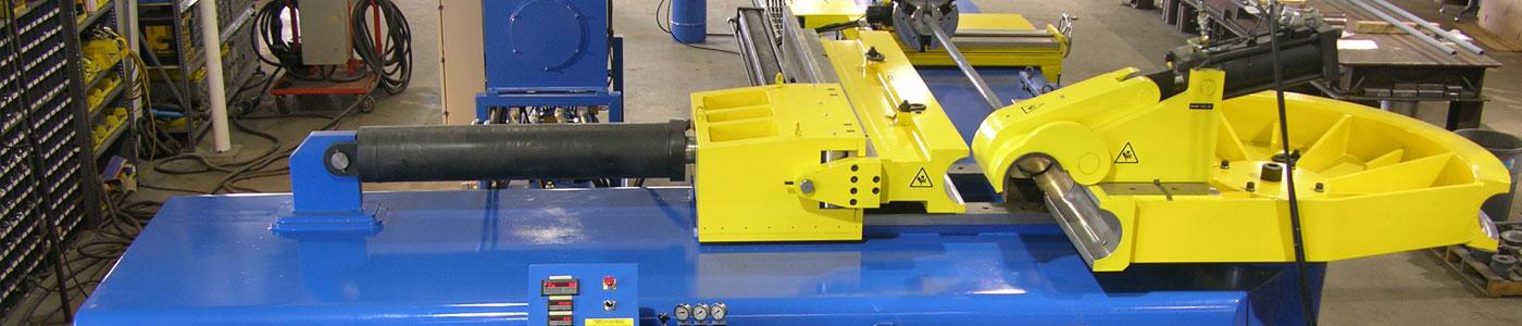
Fig. 1 A Jesse Co.1004-PC powered carriage bender - 4" Sch. 80 IPS capacity (114 x 8.5 mm).
20'-0" load length is standard on all Jesse Engineering 1000-PC series benders.
BENDERS FOR TODAY
1000-PC series "powered carriage" benders are operator controlled (non-CNC) 3-axis benders - hydraulically powered on all axes. With the proper bending tools, they have the power, accuracy, and rigidity to produce wrinkle free bends, with a minimum of ovality and wall thinning, in pipe and tubing of various metals and alloys.
Jesse Co. benders are engineered and built to state of the art machine tool standards, including JIC. Their capacities are stated in terms of Sch. 80 pipe - not a thin-wall tube whose section modules may only be half as great. Standard capacities are: 3", 4", 6", 8" IPS (60.3, 88.9, 114.3, 168.2, 219mm) - and larger.
AN IMPROVED DESIGN
Benders are more rugged, and versatile than traditional "swing arm" benders. Because no swing arm or pressure die mechanism hangs below the plane of the bend die, the main frame of a 1000-PC series bender is positioned where it ought to be, directly beneath and supporting the pressure die slide (Fig. 4). Thus, all the bending forces - exerted by the spindle and resisted by the pressure die - are directly "resolved" within a single, compact heavy duty, tubular beam. Jesse Engineering 1000-PC series benders also have the largest spindle and bearing diameters, the greatest spread between bearings, and the smallest distance from bend die to upper spindle bearing - all to insure the greatest possible rigidity.
ADVANTAGES OF 3-AXIS "POWERED CARRIAGE" BENDERS
There are several reasons for choosing an operator controlled 3-axis "powered carriage" bender.
The powered indexing carriage, which advances and rotates the workpiece between bends is not used for actually forming of the bend. On a large bender it is primarily a material handling mechanism - although it will position the workpiece for each bend just as accurately as the carriage of a CNC bender. One of the most important benefits of the powered carriage on a larger bender is that it providespowered loading, positioning, and unloading of heavy workpieces, especially when the pipe or tube must be drawn many feet over a snug fitting mandrel.
The carriage provides safe, accurate, one-man, powered positioning for distance-between-bends and plane-of-bend movements. Positioning is achieved by use of digital read-outs on each axis. There is no longer any need for the operator and a couple of helpers to be constantly wasting hours positioning heavy pipes and tubes to scribed marks and leveling meter readings.
Any CNC control system is inherently much more complex than the controls on a powered carriage bender. Therefore, powered carriage benders are ideal for situations where absolute reliability and accuracy is more important than maximum through put, or where ease of operator familiarization is desirable, or where machine use may be intermittent.
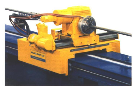 Fig. 2 The carriage on a Jesse Co. 1000-PC series bender incorporates powered centerline radius adjustment, for ease of set up, and offers two chuck or collet options - to best meet your bending needs.
INTEGRAL ("OVERHEAD") CLAMP
By mounting the hydraulic clamping mechanism on the rotating bend die itself, Jesse Co. has eliminated the conventional swing-arm (Fig. 4). There are many advantages to this system.
Built-in clamp alignment in the matching mounting surfaces of the clamp mechanism and bend die assure that no vertical or horizontal clamp set-up adjustment is required. Therefore tool changing is faster and easier.
The clamp opens upwards, eliminating interference with the forward feed of the bent workpiece. Potential interference between the clamp and the advancing workpiece is a major shortcoming of traditional swing arm benders. This problem is usually overcome by the use of a cam or linage type drop-down clamping mechanism or by a separately pivoted coaxial swing arm and main shaft. Both are complex, compromise "fixes". Jesse Co.'s overhead clamp system eliminates this problem.
Clamping forces are self contained - not carried through the die mount, the spindle, or any other part of the machine. Thus, there is never any bend-die tilt caused by clamping forces.
No overhead tie bar is required with an overhead clamp, because there is no clamp-pressure induced bend die tilt - even when bending the heaviest or most "critical" workpieces.
Tooling remains properly aligned because the bend die rotates in a level plane throughout the bend.
Machine and tooling maintenance are reduced. There are no swing arm slides or toggle linkages to wear or break, and less stress and wear on the tooling.
Overhead clamping is safer. The dangerous "pinch point" between the swing arm and pressure die arm is gone.
The operator has direct control of the clamping forces. They are easily read on a pressure gauge and easily set with a relief valve, assuring consistent, accurate set-ups. (Toggle type clamp mechanisms generate unreadable, and necessarily excessive, forces at their top-dead-center, pre-lock up position.)
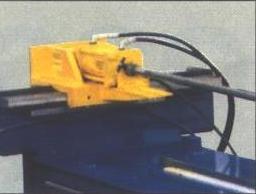 Fig. 3 The mandrel extractor unit incorporates both powered centerline radius set-up adjustment and lead screw mandrel tangent position setup adjustment - a major improvement over the old method of screwing the mandrel in and out on the mandrel rod.
CARRIAGE/MANDREL SYSTEM
The carriage/mandrel beam incorporates the mandrel extractor cylinder and mandrel rod supports together with the ways for the carriage.
The basic bender is complemented by the carriage/mandrel beam unit, without design compromises to either. Because the main beam and drive cylinders are under the pressure die slide, rather than under the mandrel beam, as in most benders, the carriage is designed to accommodate the centerline height of the bender's tooling, not vice versa. When a carriage is added to a traditional swing arm bender, the centerline height of the bend die must be elevated to accommodate the carriage collet's height above the main beam. This extra tooling height compounds the risk of bend die tilt. Jesse Co.'s 1000 series design eliminates that problem. The standard 20' (6.1m) carriage travel and load length is also not restricted by the bender's main beam length and does not require an extended frame or other modifications.
The carriage rides on precision ground, round ways for smooth travel (distance-between-bend movement) - driven by a powerful hydraulic motor through a rack and pinion. During the bending cycle, this drive is declutched to allow free towing of the carriage as the tube is drawn around the radius die.
Chuck rotation (plane-of-bend movement) is also hydraulically driven, through an extremely low-backlash worm gear. For greater accuracy, the plane of bend rotation encoder is directly driven from the worm gear drive shaft, without any secondary drive mechanism.
Two collet/chuck options are available, a jaw type chuck for heavy walled or pre-flanged tube or a collet mechanism for thinner walled tube. the carriage and chuck/collet have sufficient power and grip to sustain all movements on both axes within the machine's capacity.
Mandrel rod/workpiece supports within the beam automatically retract as the carriage passes overhead.
Powered centerline radius adjustment of the carriage and the mandrel unit during set-up is optional on 1000-PC series benders.
20' (6.1m) over-mandrel load length and carriage travel assure being able to load full pipe lengths in one continuous motion with no hitch feeding. Greater load lengths are available.
Mandrel tangent position set up adjustment is accomplished by a lead screw on the mandrel extractor cylinder - an improvement over the traditional method of screwing the mandrel in and out on the end of the mandrel rod.
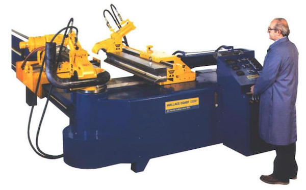
Fig. 4 The "overhead clamp" on top of the radius die opens out of the path of the advancing workpiece.
This machine is a booster bender with a second clamp - the booster clamp - on the rear of the pressure
die. Booster bending permits right radius bends with a minimum of wall thinning.
PRESSURE DIE SYSTEM
The pressure die mounts on a massive master-bar carrier riding on oversized ways which are attached directly to the main beam - not to a cantilevered arm.
The direct acting pressure die cylinder is mounted in the centerline plane of the tube to directly resist the bending forces.
The pressure die carrier slide and the masterbar are long enough to permit making 3xD 90º bends at the machine's rated capacity. (Greater lengths are available).
All set up pressure adjustments are made from the control console with pressure gages.
An automatic pressure die/carriage collision protection circuit prevents damaging collisions which can otherwise occur through operator error - i.e. due to closing the pressure die when the carriage has been advanced into the pressure die area.
OPTIONAL PRESSURE DIE ASSIST (OR BOOSTER)
FOR REDUCED WALL THINNING
Unlike other benders, the pressure die assist and booster systems on Jesse Co. 1000-PC series benders are not "add-ons". The pressure die assist/booster cylinder is integrated into the pressure die carrier head - parallel to the centerline of the workpiece, where it ought to be, so that it won't impose any asymmetrical loads. The massive pressure die carrier ways on Jesse Co. 1000 series benders can accommodate the loads imposed by a booster system. Both the lateral pressure die assist/boost pressure are adjustable from the control console through reference gauges.
Pressure die assist bending (optional) involves the use of controlled push-force applied to the pressure die. This reduces tool drag and helps control workpiece thinning. However, since the pressure die is not clamped to the workpiece, total assist force is limited by the co-efficient of friction between the pressure die and the tube. Pressure die assist bending is not the same as booster bender.
Booster bending (optional) involves a continuous push-force applied directly to the workpiece through a booster clamp. To achieve maximum booster effect, the booster cylinder and its mounting system must be able to exert a sufficient load to bring the workpiece close to compressive yield. With the Jesse Co. boost system, the booster clamp is mounted directly on the rear of the pressure die, which then provides continuous column strength reinforcement of the workpiece under high booster loads (Fig. 4). A sequence of four pre-selected boost pressures are automatically applied as designated degree-of-bend points are reached.
"Shaped groove" no-mandrel bending combines special tools with pressure die assist (or optional boost for shorter radius bends) permitting non-mandrel bending of a broad range of pipe and heavier walled tube while minimizing wall thinning and ovality.
OPERATOR CONTROLS
All functions are controlled by handlever valves, combined with digital position displays for all three axes.
(Fig. 4) The bend axis has a digital degree-of-bend controller, with up to 14 programmable pre-sets, controlling both a slow down valve and a stop valve for maximum bend accuracy. The operator simply pulls the "BEND" lever until the spindle automatically stops at the desired degree-of-bend. the distance-between-bends display counts in either direction of motion from a zero reference point, which can be reset to a new position at any time. The operator pulls the lever until the read out shows that the desired position has been reached. The plane-of-bend axis functions identically to the distance-between-bends axis, but with the display in degrees, rather than inches or millimeters.
Hand lever controls are safer than push button solenoid valves because the operator's hand must always be on the control lever. The operator is safely at the control station during the bend cycle - and the machine stops the moment the lever is released.
Hand Levers allow greater operator control. They can be "cracked" open for low speed or small incremental moves - unlike push button solenoid valves, which are either "ON" or "OFF".
Control lever operation of a 1000-PC bender is ergonomically designed. The direction of lever movement coincides with the resultant machine movement and/or is simply logical. The levers are sequenced, in functional order, from the operator's left to right.
The bend cycle controls are:
1. CLAMP: pull = clamp / push = open.
2. PRESSURE DIE: pull = close / push = open.
3. MANDREL: pull = forward / push = back.
4. BEND: pull = bend / push = return. (Also returns masterbar).
5. MASTERBAR: pull = advance / push = return.
(Only used for set-up. During bending the masterbar, which carries the pressure die, advances with the tube. When the bend die is returned, the masterbar automatically returns first.) Because the masterbar control lever is not normally used by the operator, this is called a "four-Lever" Control System.
The three carriage function controls are grouped separately to the right of the bending function controls:
1. DISTANCE-BETWEEN-BENDS: pull = carriage advance / push = carriage back.
2. PLANE-OF-BEND: pull = clockwise rotation / push = counter-clockwise rotation.
3. CHUCK/COLLET: pull = close / push = open.
Pressure gages on the control panel show pressure readings for the Clamp, Pressure Die, and Pressure Die Assist/Boost Cylinders, and for the Chuck/Collet.
Electronic and hydraulic control components on the machine either are located away from points where they might be struck by workpieces during loading and unloading, or are provided with protective guarding.
MACHINE TOLERANCES
The accuracy of the workpiece produced by a bender can be no better than the machine.
Jesse Co. benders are accurate:
- C-Axis/Degree-of-Bend (Bend Spindle) to ±0.1º
- B-Axis/Plane-of-Bend (Collet/chuck Rotation) to ±0.2º
- Y-Axis/Distance-Between-Bends (Carriage Travel) to ±0.06"
OTHER OPTIONS AVAILABLE
- Pressure Die Assist
- A mandrel lubricator system which pumps heavy lubricant - Jesse Co. BEND EZ - through the hollow mandrel rod and out through holes in the side of the mandrel.
- Powered cross slides, push button operated, in lieu of hand wheels.
- A central machine lubricator system which automatically lubricates critical bearings and ways.
- An oil heater/cooler for machines operating under extreme, or extremely variable, temperature conditions.
| Specifications | 1003PC | 1004PC | 1006PC | 1008PC |
| Maximum Pipe Size | 3/80 | 4/80 | 6/80 | 8/80 |
| Maximum OD | 4.0" | 5.0" | 8.0" | 10.0" |
| Minimum OD (suggested) | 0.84" | 1.030" | 2.375" | 3.500" |
| Wall Thickness @ Max OD | .1875" | .1875" | .250" | .250" |
| Maximum CLR | 15" | 12" | 18" | 24" |
| Maximum Spindle Rotation | 193º | 193º | 193º | 193º |
| Maximum Length over mandrel | 20' | 20' | 20' | 20' |
| Working Height | 42" | 42" | 42" | 50" |
| Tooling Centerline Height | 2.500" | 3.000" | 4.375" | 6.000" |
| Mandrel Stroke | 7" | 10" | 14" | 18" |
| Follower Stroke | 31" | 42" | 61" | 44" |
| Pressure Die Stroke | 5" | 6" | 8" | 10" |
| Hydraulic Tank Capacity | 10 gal. | 20 gal. | 40 gal. | 80 gal. |
| Hydraulic System Pressure | 2500 psi | 2500 psi | 2500 psi | 2500 psi |
| Length Rearwards (approx.) | 26' | 26' | 27' | 29' |
| Length Forwards | 10" | 12" | 16" | 24" |
| Mandrel Rod OD | 1.66" | 1.90" | 2" | 2" |
| Mandrel Thread | 1.25"-12 | 1.75"-10 | 2"-12 | 2"-12 |
| Overall Width (approx.) | 78" | 108" | 10' | 19' |
| Height (approx.) | 54" | 56" | 60" | 78" |
| Weight (lbs) (approx.) | 11,000 | 16,000 | 24,000 | 34,000 |
| Speeds | ||||
| C-Axis Fwd/Rev (rpm) | 1.3 / 3.2 | 1.0 / 3.4 | .60 / 2.2 | .50 / 1.5 |
| B-Axis (rpm) | 2 | 1.5 | 1.0 | .75 |
| Y-Axis (fpm) | 40 | 35 | 30 | 20 |
Specifications, capacities, and design features described are subject to change without notice.